2016年1月4日星期一

Start a corrugated box plant or Carton box manufacturing company

Start a corrugated box plant or Carton box manufacturing company

How to choose corrugator machine for starting a corrugated box plant or Carton box manufacturing company,a small carton box manufacturing unit ?
I am a salesman of corrugated box making machine in China, there are almost 300 manufacturers in my county-Dongguang county, I promise you can find every machine you need to start carton box plant.
Corrugated carton box manufacturing plant and factory
If you plan to set up the carton box plant, you need know the machine types at first, there are many machines:3/5 ply corrugated sheet production line producing corrugated sheet to convert carton box,mostly you don’t need unless you have a huge business, for small carton box plant, you can purchase corrugated sheet from other company,then purchase corrugated sheet cutting machine to cut sheet, slitting and scoring machine to make the cutted sheet into right shape for box, flexo printing machine print beautiful photo on it, box folder machine fold the slitted sheet to packed,stiching machine or gluing machine make plat sheet into cube box,the rotary die cutting machine can replace slitting and scoring machine to cutting non-standard box.
Dongguang Corrugated Box Making Machinery Group is one of the largest Corrugated Carton & Box Making Converting Printing Machines Equipments manufacturers in China, supply high quality machines and good service for corrugated box plants wordwidely. We are specialized at corrugated box carton & cardboard machines . Corrugated sheet making machine, corrugated sheet cutter, boardcard slitter, flexo printing press, box folder & gluer, corrugated cardboard die-cutting machines. Anything you have interested, please contact me : corrugatedboxmachine@hotmail.com 

ASTM A182 F12 Forged or Rolled Alloy and Stainless Steel Pipe Flanges, Forged Fittings

ASTM A182 F12 Forged or Rolled Alloy and Stainless Steel Pipe Flanges, Forged Fittings


ASTM A182
Standard Specification for Forged or Rolled Alloy and Stainless Steel Pipe FlangesForged Fittings, and Valves and Parts for High-Temperature Service
1. Scope
1.1 This specification covers forged low alloy and stainless steel piping components for use in pressure systems. Included are flangespipe fittings, Valves, and similar parts to specified dimensions or to dimensional standards, such as the ASME specifications that are referenced in Section 2.
1.2 For bars and products machined directly from bar (other than those directly addressed by this specification; see 5.4), refer to Specifications A 479/A 479M and A 739 for the similar grades available in those specifications. Products made to this specification are limited to a maximum weight of 10 000 lb [4540 kg]. For larger products and products for other applications, refer to Specifications A336/A336M and A 965/A 965M for the similar ferritic and austenitic grades, respectively, available in those specifications.
1.3 Several grades of low alloy steels and ferritic, martensitic, austenitic, and ferritic-austenitic stainless steels are included in this specification. Selection will depend upon design and service requirements.
1.4 Supplementary requirements are provided for use when additional testing or inspection is desired. These shall apply only when specified individually by the purchaser in the order.
1.5 This specification is expressed in both inch-pound units and in SI units. However, unless the order specifies the applicable “M” specification designation (SI units), the material shall be furnished to inch-pound units.
1.6 The values stated in either inch-pound units or SI units are to be regarded separately as the standard. Within the text, the SI units are shown in brackets. The values stated in each system are not exact equivalents; therefore, each system must be used independently of the other. Combining values from the two systems may result in nonconformance with the specification.
 CMnPSSiNiCrMoVCuOther
A182 F50.15 Max0.30-0.600.035 Max0.030 Max0.50 Max0.50 Max4.0-6.00.44-0.65
A182 F90.15 Max0.30-0.600.030 Max0.030 Max0.50-1.00 8.0-10.00.90-1.10   
A182 F110.10-0.20 (2)0.40-0.650.025 Max0.040 Max0.50-0.801.00-1.500.44-0.65
A182 F220.05-0.150.30-0.600.035 Max0.040 Max0.50 Max2.00-2.500.90-1.10
A182 F910.08-0.120.30-0.600.020 Max0.010 Max0.20-0.500.40 Max8.0-9.50.85-1.050.18-0.25Cb, 0.06-0.10; N, 0.03-0.07; Al, 0.04 max.

MSS SP-95 Swaged Pipe Nipples Dimensions

MSS SP-95 Swaged Pipe Nipples Dimensions


MSS SP-95 swage nipples dimensions
MSS SP-95 Swaged Nipples and Bull Plugs covers dimensions, finish, tolerances, marking and material for carbon steel and alloy steel Swaged Nipples (male end reducing fittings), NPS 1/4 through NPS 12 and Bull Plugs (hollow or solid male closures) NPS 1/8 through NPS 12. These fittings are made with ends that are threaded, beveled, square cut, grooved, or any combination of these. Both concentric and eccentric swaged nipples are included.

NPSOutside Diameter 
 D1(Large End)D2(Small End)A(End To End)
1/4″x1/8″13.710.357
3/8″x1/8″17.110.364
3/8″x1/4″17.113.764
1/2″x1/8″21.310.370
1/2″x1/4″21.313.770
1/2″x3/8″21.317.170
3/4″x1/8″26.710.376
3/4’x1/4″26.713.776
3/4″x3/8″26.717.176
3/4″x1/2″26.721.376
1″x1/8″33.410.389
1″x1/4″33.413.789
1″x3/8″33.417.189
1″x1/2″33.421.389
1″x3/4″33.426.789
11/4″x1/8″42.210.3102
11/4″x1/4″42.213.7102
11/4″x3/8″42.217.1102
11/4″x1/2″42.221.3102
11/4″x3/4″42.226.7102
1 1/4″x1″42.233.4102
11/2″x1/8″48.310.3114
11/2″x1/4″48.313.7114
11/2″x3/8″48.317.1114
11/2″x1/2″48.321.3114
11/2″x3/4″48.326.7114
1 1/2″x1″48.333.4114
11/2″x11/4″48.342.2114
2″x1/8″60.310.3165
2″x1/4″60.313.7165
2″x3/8″60.317.1165
2″x1/2″60.321.3165
2″x3/4″60.326.7165
2″x1″60.333.4165
2″x1 1/4″60.342.2165
2″x1 1/2″60.348.3165
2 1/2″x1/8″7310.3178
2 1/2″x1/4″7313.7178
2 1/2″x3/8″7317.1178
2 1/2″x1/2″7321.3178
2 1/2″x3/4″7326.7178
2 1/2″x1″7333.4178
21/2″x11/4″7342.2178
21/2″x11/2″7348.3178
2 1/2″x2″7360.3178
3″x1/8″88.910.3203
3″x1/4″88.913.7203
3″x3/8″88.917.1203
3″x1/2″88.921.3203
3″x3/4″88.926.7203
3″x1″88.933.4203
3″x1 1/4″88.942.2203
3″x1 1/2″88.948.3203
3″x2″88.960.3203
3″x2 1/2″88.973203
3 1/2″x1/8″101.610.3203
3 1/2″x1/4″101.613.7203
3 1/2″x3/8″101.617.1203
3 1/2″x1/2″101.621.3203
3 1/2″x3/4″101.626.7203
3 1/2″x1″101.633.4203
31/2″x11/4″101.642.2203
31/2″x11/2″101.648.3203
3 1/2″x2″101.660.3203
31/2″x21/2″101.673203
3 1/2″x3″101.688.9203
4″x1/4″114.313.7229
4″x3/8″114.317.1229
4″x1/2″114.321.3229
4″x3/4″114.326.7229
4″x1″114.333.4229
4″x1 1/4″114.342.2229
4″x1 1/2″114.348.3229
4″x2″114.360.3229
4″x2 1/2″114.373229
4″x3″114.388.9229
4″x3 1/2″114.3101.6229

Jiangsu Yulong steel pipe start the mill construction in Nigeria

Jiangsu Yulong steel pipe start the mill construction in Nigeria

Yulong steel pipe company is one of the biggest steel pipe manufacturer in China, which has more than 2800 employees and 20 sets of steel pipe processing and manufacturing lines.  
Yulong steel pipe company planed to invest $50 millions in Nigeria from their HongKong Branch ,and establish two steel pipes processing lines, they have completed bush clearing works and sand filling of an 180000 ㎡ expanse of land in preparation for the construction of a steel mill.  it will be the largest steel pipe mill in Lekki Free Zone when it finish.  It will help the China steel pipes manufacturer to enter the Nigeria markets deeply.
jiangsu-yulong-steel-pipe-start-the-mill-construction-in-nigeria

This new pipe mill development is in compliance with the Federal Government Local Content Act, it will be the first Oil and Gas Pipe manufacturer to commence the production of Steel pipes in Nigeria. The main pipe products in this mill is longitudinal submerged arc welded pipe .
The ground breaking ceremony for the Steel Pipe plant is scheduled to hold towards the end of October while actual construction will commence in November 2015 as the fabrication of the steel structure for the factory house has commenced in China. 
The Company production capacity is estimated at about 400,000 tonnes per year. The demand for these steel pipes will be driven by oil field developments and crude production, industrial and domestic natural gas distribution projects  and export gas pipeline projects. It also include LNG and other process plants, fabrication yards and construction industry and regional oil and gas development and infrastructure pipe network like the West Africa Power Pool and Trans Saharan Gas Project.  The mill project also will bring around 5000 jobs in Nigeria.

EN 1759-1 Circular flanges for pipes, valves, fittings- Part 1 : Steel flanges, NPS 1/2 to 24

EN 1759-1 Circular flanges for pipes, valves, fittings- Part 1 : Steel flanges, NPS 1/2 to 24


BS EN 1759-1:2004 Standard for a single system of flanges specifies requirements for circular steel flanges in Class designations Class 150 to Class 2 500 and nominal sizes from NPS to NPS 24.
This standard specifies the flange types and their facings, dimensions, tolerances, threading, bolt sizes, flange jointing face surface finish, marking, materials and pressure/temperature ratings.
This standard does not apply to flanges made from bar stock by turning, or to flanges of types 11, 12, 13, 14 and 15 made from plate material.

This standard specifies the flange types and their facings, dimensions, tolerances, threading, bolt sizes, flange jointing face surface finish, marking, materials and pressure/temperature ratings. This standard does not apply to flanges made from bar stock by turning, or to flanges of types 11, 12, 13, 14 and 15 made from plate material.
Information to be supplied by the equipment manufacturer :
The following information should be supplied by the equipment manufacturer in the enquiry and/or order. Flanges and ancillary components in accordance with this standard shall be designated with the following:
a)Designation, e.g. flange, lapped or collar;
b)Number of this standard, EN 1759-1;
c) Flange type number;
d) Facing type number;
e) Nominal size (NPS or DN);
f) Class designation followed by the appropriate number;
g) The bore for weld-neck (type 11) and hubbed slip-on (type 12) flanges, if different from those specified in this standard.
h) Weld end preparation required;

JIS B2316 Steel Socket-welding pipe fittings

JIS B2316 Steel Socket-welding pipe fittings


JIS B2316 Socket Weld Y Tee
JIS B2316 Socket Weld Tee
JIS B2316 Socket Weld Tee
JIS B2316 Socket Weld Cap
JIS B2316 Socket Weld Cap
JIS B2316 Socket Weld Cross
JIS B2316 Socket Weld Cross
 

2016年1月3日星期日

DIN 2448 Seamless and welded steel pipes-EN 10220

DIN 2448 Seamless and welded steel pipes-EN 10220


Standard: DIN2448
Steel Grade: St37, St45, St52
DIN 2448:Seamless and welded steel tubes – Dimensions and masses per unit length; German version EN 10220:2002
DNOuter Dimenesion
1017.2
1521.3
2026.9
2533.7
3242.4
4048.3
5060.3
6576.1
8088.9
100114.3
125139.7
150168.3
175193.7
200219.1
250273
300323.9
350355.6
400406.4
450457
500508
600610
DIN 2448 ST37.0 seamless steel pipes

ANSI/ASME B16.25 - Buttwelding Ends

ANSI/ASME B16.25 - Buttwelding Ends


This Standard covers the preparation of buttwelding ends of piping components to be joined into a piping system by welding. It includes requirements for welding bevels, for external and internal shaping of heavy-wall components, and for preparation of internal ends (including dimensions and tolerances).
Coverage includes preparation for joints with the following: no backing rings; split or noncontinuous backing rings; solid or continuous backing rings; consumable insert rings; gas tungsten arc welding (GTAW) of the root pass.
ANSI/ASME B16.25 Standard covers the preparation of butt welding ends of piping components to be joined into a piping system by welding. It includes requirements forwelding bevels, for external and internal shaping of heavy-wall components, and for preparation of internal ends (including dimensions and tolerances).
ASME B16.25 - Buttwelding Ends dimensions and tolerances
ASME B16.25 – Buttwelding Ends dimensions and tolerances

Coverage includes preparation for joints with the following:
(a) no backing rings
(b) split or noncontinuous backing rings
(c) solid or continuous backing rings
(d) consumable insert rings
(e) gas tungsten arc welding (GTAW) of the root pass Details of preparation for any backing ring must be specified when ordering the component.
ANSI/ASME B16.25 Standard applies to any metallic materials for which a welding procedure can be satisfactorily qualified, but does not prescribe specific welding processes or procedures. Unless otherwise specified by the purchaser, it does not apply towelding ends conforming to ASME B16.5ASME B16.9, or ASME B16.47. Send us your technical drawings: Haihai Group will supply you with whatever flanges you are looking for.
ASME B16.25 - Buttwelding Ends
ASME B16.25 – Buttwelding Ends

Nominal wall Thickness : tEnd Preparation
t<5mm (for austenitic alloy steel t<4mm)Cut square or slightly chamfer at manufacturer ‘ s option
5<t<22mm (4<t<22mm)Plain Bevel as in sketch ( a ) above
t>22mmCompound Bevel as in sketch ( b ) above

WELDBEND NOTES:
Weld neck Flanges can be joined to pipe of lesser wall with proper end preparation and joint design. The recommendations that follow apply to weld neck flanges with standard plain end bevels (as shown above) and with a hub thickness at the bevel no greater than 1 1/2 times the mating pipe thickness.
The thickness of the flange hub at the weld bevel and the pipe shall be in accordance with the design requirements of the applicable section of ASME B31 Code for Pressure Piping. When the internal offset due to unequal thickness does not exceed 1/2 times the pipe wall thickness, then the rules and figures given on page 75 are recommended as well for joining weld neck flanges to pipe of lesser wall and/or higher strength.
When the additional thickness of the hub at the bevel results in an offset at the outside diameters of the ends to be joined, reference should be made to ASME B31 and ASME B16.5 Bevel Wall Thickness (t) 0.19 In. To 0.88 In. Inclusive A = Outside Diameter of flange and mating pipe (inches) B = Inside Diameter of flange (inches) t = Wall thickness of flange hub at bevel (inches) Note: For bevel wall thickness over .88″ refer to ASME B16.5 for alternative detail.

JIS G3101 General Structure Hot Rolled SS400 Steel

JIS G3101 General Structure Hot Rolled SS400 Steel


JIS G3101 SS400 JIS G3101 SS400 steel plate/sheet, under JISG3101 standard, we can regard SS400 steel plate/sheet for general purpose structural steel.
JIS G3101 SS400 is a technical delivery conditions for general purpose structural steel, and a type of steel sheet under JIS standard which is used to build ship, bridge, belongs to high strength sheet.

What is SS400 Steels?

SS400 steel is a structural hot Rolled steel in the form of plates, sheets & strips for general structural applications. SS400 is a material grade and designation defined in JIS G 3101 standard. JIS G 3101 is a Japanese material standard for hot Rolled steel plates, sheets, strips for general structural usage.
The structural quality hot rolled SS400 steel is more reliable in its tensile strength than SS330 steel. Dimensional Characteristics of SS400 Steels: The applicable thickness for this SS400 material as defined in the JIS 3101 starts from 6 mm to 120 mm.
The Chemical Composition of SS400 Steels as under:
Carbon (C) is not identified in the standard. Manganese (Mn) is not identified in the standard.
Maximum percentage of Phosphorous (P) is 0.050 percent.
Maximum percentage of Sulphur (S) is 0.050 percent. Remaining is iron (Fe) percentage and with few negligible impurities.

JIS G 3101 SS400 Steel Mechanical Properties :

Density: 7860kg/m3
Young’s Modulus: 190-210GPa
Tensile Strength: 400 – 510 MPa
Yield Strength: 205-245 MPa
Poisson’s ratio: 0.26
Hardness Brinell Hardness: 160HB
The tensile strength of the SS400 Steels is expressed in Newton per millimeters and it must be at-least 400 N/mm2 (MPa) and maximum can be 510 N/mm2 (MPa).
The yield strength is minimum 205 to minimum 245 N/mm2 (MPa) depending on the thickness.
The yield strength for thickness below 16 mm is minimum 245 N/mm2 (MPa) whereas for higher gauges above 100 mm is minimum 205 N/mm2 (MPa).
The elongation property of SS400 steel varies with the ranges of thickness.  The minimum percentage ranges for elongation is 17% thicknesses till 16 mm, 21% for thicknesses till 40 mm, and 23% greater than 50 mm.
SPHC steel comparison with this grade of SS400 material will show how general structure hot rolled steel differs with commercial quality SPHC steel in chemical composition & mechanical properties.
Applications of this kind of steel are in making structural tubes, pipes, rods, and various structural sectional steels.
JIS G3101 SS400 is equivalent to DIN:St37-2,EN SS400,ASTM:A283C and UNI:FE360B. Equivalent grade : SS400 steel plate/sheet is in JIS G3101 standard. The equal material of SS400 is: BS 4360 40(A)B, CSAG40-21 230 G, IS IS 226, JIS 3106 SM 400 A – ISO 630 Fe 360 B, ASTM A 36/A 283 C.
JIS G3101 SS400Comparision of steel grades
BS 436040(A)B
CSAG40-21230 G
ISIS 226
JIS 3106SM 400 A
ISO 630Fe 360 B
ASTMA 36/A 283 C
JIS G3101 SS400 steel Mechanical Properties JIS G3101 SS400 steel plate/sheet for carbon steels, This kind of steel has very wide use. Because of the low Carbon content and without alloy element, carbon structural steel has the proper tensile strength, good toughness, plasticity,processing property. More detailed information about JIS G3101 SS400 steel Mechanical Properties , please refer to the following table:
GradeYield Strength(Mpa)Tensile Strength(Mpa)Elongation min.(%)
JIS G3101 SS400Thickness Thickness
 <16 mm≥16mm <5mm5-16mm≥16mm
 245235400-510211721

120 pcs hot induction bends are arranged heat treatment in haihao pipe fitting factory.

Finally, hebei haihao pipe fitting factory proceeded the heating treatment for 120 pcs hot induction bends .  They are from the new order of 920 pcs 5D hot induction pipe bends.
sand-blasting-induction-bend
These bends specification is 12″, 5D, 180 Degree, the bend without any tangent length on the two ends, material is API 5L GR.B.  Coating finish is black painted , they are all normal requirements in our regular production .after the hot induction bending process, we do this step of heat treatment.
hot-induction-bends-order
For the steel pipe fittings , suitable heat treatment is necessary to get a good quality performance. As per the clients request , we arranged heat treatment for all the bends at a temperature of 600 ℃, it can make sure the high quality request of the project and end user.
hot-induction-bends-order
It is a little raining today here in Hebei, but it did not delay the heat treatment working in our factory. our 12.5meter * 4.5meter heating treatment furnace workshop operated very good in such weither , finally we finish the work as per the plan ,it will not effect the delivery time of this bends order .

Spectacle Flange, Spades and Ring-Spacers

spectacle flange is a safety device used to isolate a section of line or piece of equipment when the line or equipment needs to be inspected or removed from service. It is different than a valve in that the blind is a permanent or long term isolation device.
spectacle flange is machined from a single piece of metal that is cut to match the pipe size, fit between two pipe flanges and requires an additional gasket when it is installed. Also, the bolts will need to be lengthened depending on what piping class and size blind is used. The thickness of the spectacle flange is specified based on the line pressure and pipe size.
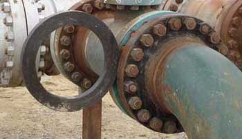
Ring Spacer
Ring spacers are bored to the matching pipe ID and are the same thickness as the “single blind” that it replaces. When removing a “single blind”, either the flange and associated piping must be pulled together to seal the line, or a “ring spacer” must be installed to fill the gap. Thick single blinds or rigid piping systems normally require ring spacers.
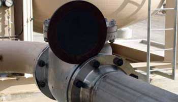
Single/Line Blind or Blank
A positive shut-off device normally installed adjacent to, or in conjunction with, a valve. Their purpose is to prevent accidental flow through a pipeline to a vessel. With the exception of cast iron, plastic, or fiberglass services, they are not drilled with bolt holes, but fit inside the bolt circle of mating flanges. Pipeline blinds or blanks are not the same as bolting blind flanges. Single blinds ues standard gaskets.
A combination of a “single blind’ and a “ring spacer” can be fabricated for field convenience as a single unit. Weight consideration and the associated difficulty of handling heavy pieces in the field are a primary consideration in specifying a “spectacle blind” or a combination of blinds. Spectacle blinds are meant to be rotated to change blind/spacer orientation.
Spectacle Blind
A spec blind is a combination of a ring spacer and single blind. They are usually permanently installed in a piping system and rotated as needed.
Spectacle blinds
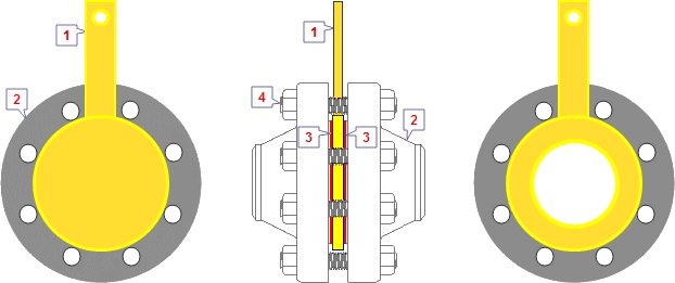
Spectacle Blinds are generally applied to permanently separating pipesystems, or just to connect with each other. A Spectacle Blind is a steel plate cut into two discs of a certain thickness.
The two discs are attached to each other by section of steel similar to the nose piece of a pair of glasses. One of the discs is a solid plate, and the other is a ring, whose inside diameter is equal to that of a flange.
Spectacle Blinds be applied in systems, which regularly need to be separated from other installations. Normally, a Spectacle Blind is mounted in the “open” position so that flow through the pipe is possible. If the Spectacle Blind in the “close” position is rotated, the pipe is blanked off and no flow is possible.
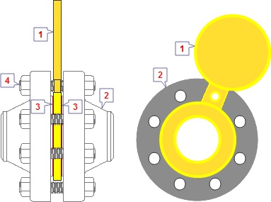
Maintenance on a pipesystem can be a reason to rotate the spectacle in the “close” position. This run will take place through the hole, that is drilled in the connection piece. By loosening of all bolts, and partial removal of their, the Spectacle Blind can be rotated. After replacing the gaskets (new gaskets are to recommend), the bolts can be re-assembled and tightened.
Spectacle blind in open position
Spectacle blind in closed position
Spades & Ring Spacers
Spades
Spades and Ring Spacers are basically the same as Spectacle Blinds, except that both are not attached to each other.
Spades and Spacers be applied in systems where maintenance is often not necessary, or in applications with large pipe sizes. Depending on the flange size and the Pressure Class, Spades can weigh hundreds of pounds. To prevent unnecessary weight to a flange connections, usually will be chosen not for a Spectacle Blind, but for 2 separate parts.
Typical Spade Typical Ring Spacer

Typical Spade and Ring Spacer
Typical Spade and Ring Spacer 1. Spade 2. Flanges 3. Gaskets 4. Stud Bolts
Ring Spacer1. Ring Spacer 2. Flanges 3. Gaskets 4. Stud Bolts
Ring Spacer1. Ring Spacer 2. Flanges
3. Gaskets 4. Stud Bolts
So as for the Spectacle Blind already described, maintenance on a pipesystem can be a reason to temporarily replace a Ring Spacer for a Spade. By loosening of all bolts, and half of the bolts temporarily remove, the Spade or Spacer can be placed. After replacing the gaskets (new gaskets are to recommend), the bolts can be re-assembled and tightened.
A small problem is that we basically can not see, or a Spade or a Spacer mounted between the flanges. Therefore the handles are often specially marked, or both have a different design; a customer often provides its own specification.
What should never lack is, that in the handle, the diameter and the Pressure Class of a Spade or Spacer is engraved; this applies also for the Spectacle Blind.
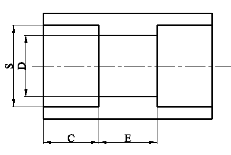
Surfaces – Dimensions – Material
The sealing surfaces of a Spectacle Blind, Spade or Ring Spacer are usually conducted in accordance with the Face Finish from the flange. The diameter always is slightly larger than the Raised Face of a flange; by a correct assembly, the bolts are just not touched by the Blind or Spacer.
The diameter of them, is depending on the flange size, and the thickness from the Pressure Class of a flange.
Dimensions from Spectacle Blinds, Spades and Ring Spacers, you will find in the main Menu “Flanges”
ASME B16.48 covers pressure-temperature ratings, materials, dimensions, dimensional tolerances, marking, and testing for operating line blanks in sizes NPS 1/2 – NPS 24 for installation between ASME B16.5 flanges in the 150, 300, 600, 900, 1500, and 2500 Pressure Classes.
Spectacle Blinds, Spades and Ring Spacers should be made from a plate or forging specification, approved for use by ASME B31.3, of essentially the same chemical composition as the mating flanges and piping involved.